


 Hi Gang…
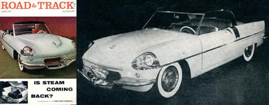
Experimental motive power, world-class designer, innovating disappearing / sliding hardtop, fiberglass body….how much intrigue and interest can you put into just one car?
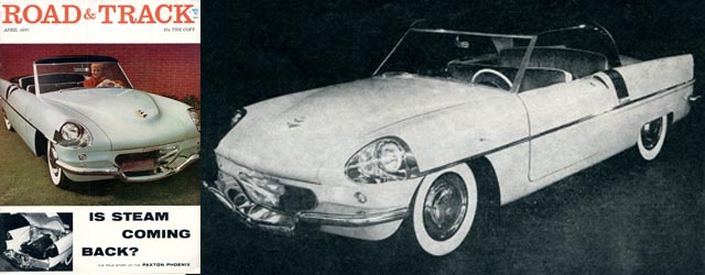
Well if you did, the best car that would fit this bill would be the Brooks Stevens designed Paxton Phoenix – cover car of Road & Track Magazine in April 1957.
Let’s see what John Bond had to say about the history of this significant car in his 1957 Road & Track Cover story.
The True Story of the Paxton Phoenix
By John Bond
The dream of every dedicated automotive designer is to start with a clean sheet of paper, unhampered by the necessity of using this or that component part which was used the year before. Sometimes such a dream actually happens–as in this case. Our story begins in 1950. In that year Robert Paxton McCulloch decided that he would fulfill a long-time ambition–to design and possibly to produce a true luxury car for the discriminating motorist who could afford the best.
As a manufacturer of two-cycle engines and related products, he had been extremely successful and could afford such a venture. His McCulloch Motors Corporation, founded in 1946, had expanded to the point that over 1500 persons were employed. His gasoline powered chain saws, though not the cheapest on the market, were out-selling his competitors on the basis of performance and a reputation for durability. Other activities included the manufacture of target plane engines, the aviation Division’s helicopter and two newly acquired divisions; Rhodes-Lewis (aircraft accessories) and Pacific Optical.
An engineer himself, Robert McCulloch was, and is, a firm believer in engineering and development. Already he had surrounded himself with some of the best engineering talent, and with this force to draw upon the Paxton Division was formed (in 1950), headed by an engineer/general manager, John C. Thompson. The Paxton Division was to be the advanced design department for many varied projects, but its biggest assignment was the car. Remarkably enough, the concept of the Paxton car was very similar to a later car which ultimately came to be known as the Continental Mark II.
However, the Paxton was originally planned to be relatively small in size (115″ wheelbase) in keeping with the already noticeable impact of expensive imported sports cars. Although not a sports car, it was to give very high performance, seat four people, and incorporate a hard top which would retract. Unwilling to rob other divisions of engineering talent, McCulloch’s progress on the car was slow in 1950. The chassis design was entrusted to an experienced and independent Detroit firm: Hoffman Motor Development Co., owned by Roscoe C. Hoffman.
This company was well known for its ability to design and build experimental cars; they had built a front wheel drive car in 1930, pioneered designs with independent suspension of all 4 wheels, and built prototype cars for several large manufacturers. At least one vehicle had a rear-mounted engine.
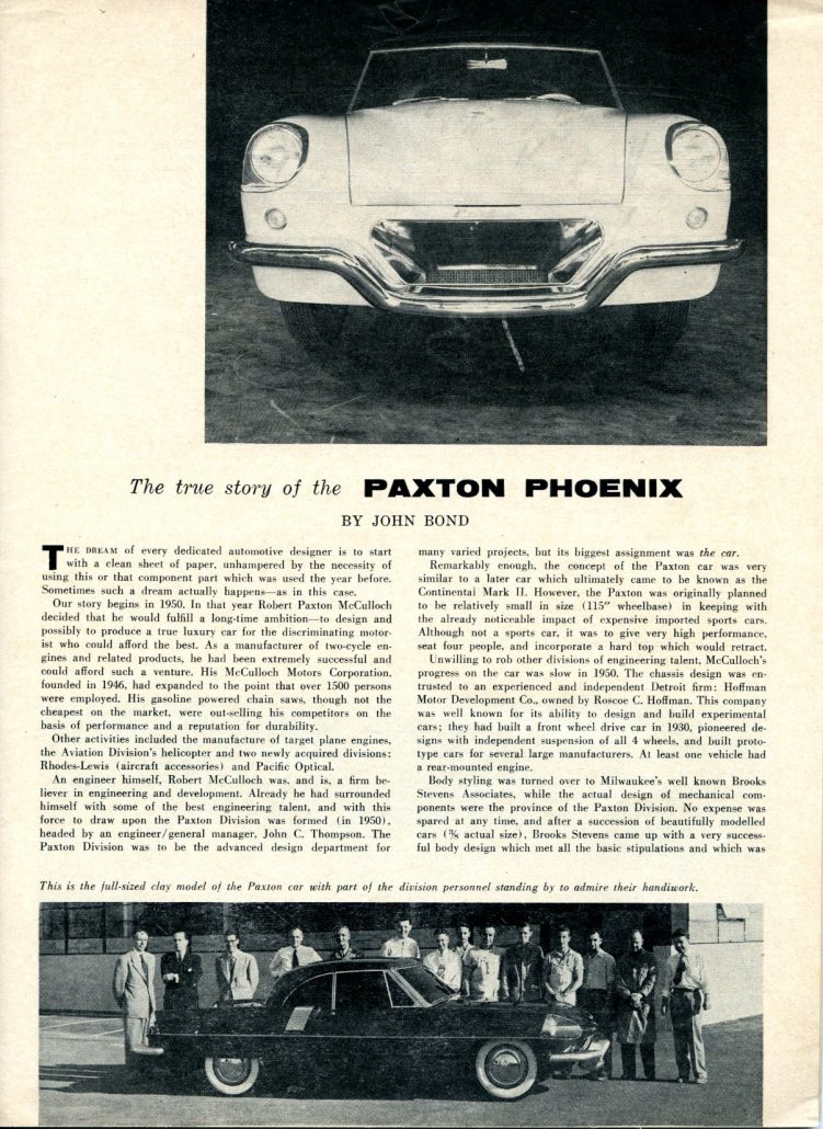
Body styling was turned over to Milwaukee’s well known Brooks Stevens Associates, while the actual design of mechanical components were the province of the Paxton Division. No expense was spared at any time, and after a succession of beautifully modeled cars (3/8 actual size), Brooks Stevens came up with a very successful body design which met all the basic stipulations and which was acceptable to the management.
The prototype bodies were to be made of fiberglass, and the first step was to build a full size clay mock-up of the car exterior. When completed late in 1951, the clay model was mounted on wheels, painted and photographed. (See bottom of page 13.) Even before the full-size clay mock-up was finished, work began on a super-accurate plaster model.
Despite an earthquake, which cracked the job when it was almost completed, the first female molds were taken off, and finished panels were ready for assembly by August of 1952. This rate of progress may seem slow, but was actually quite remarkable in view of the small body engineering crew and the fact that complete and accurate production drawings of every contour and every detail, including the power-operated top mechanism, had to be made.
Body Features:
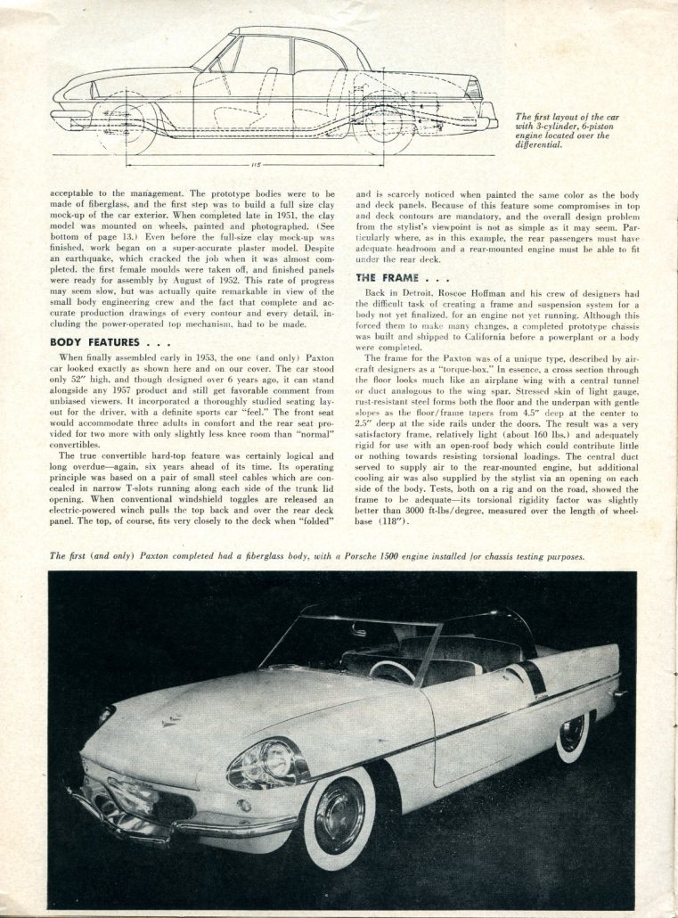
When finally assembled early in 1953, the one (and only) Paxton car looked exactly as shown here and on our cover. The car stood only 52″ high, and though designed over 6 years ago, it can stand along side any 1957 product and still get favorable comment from unbiased viewers. It incorporated a thoroughly studied seating layout for the driver, with a definite sports car “feel.” The front seat would accommodate three adults in comfort and the rear seat provided for two more with only slightly less knee room than “normal” convertibles.
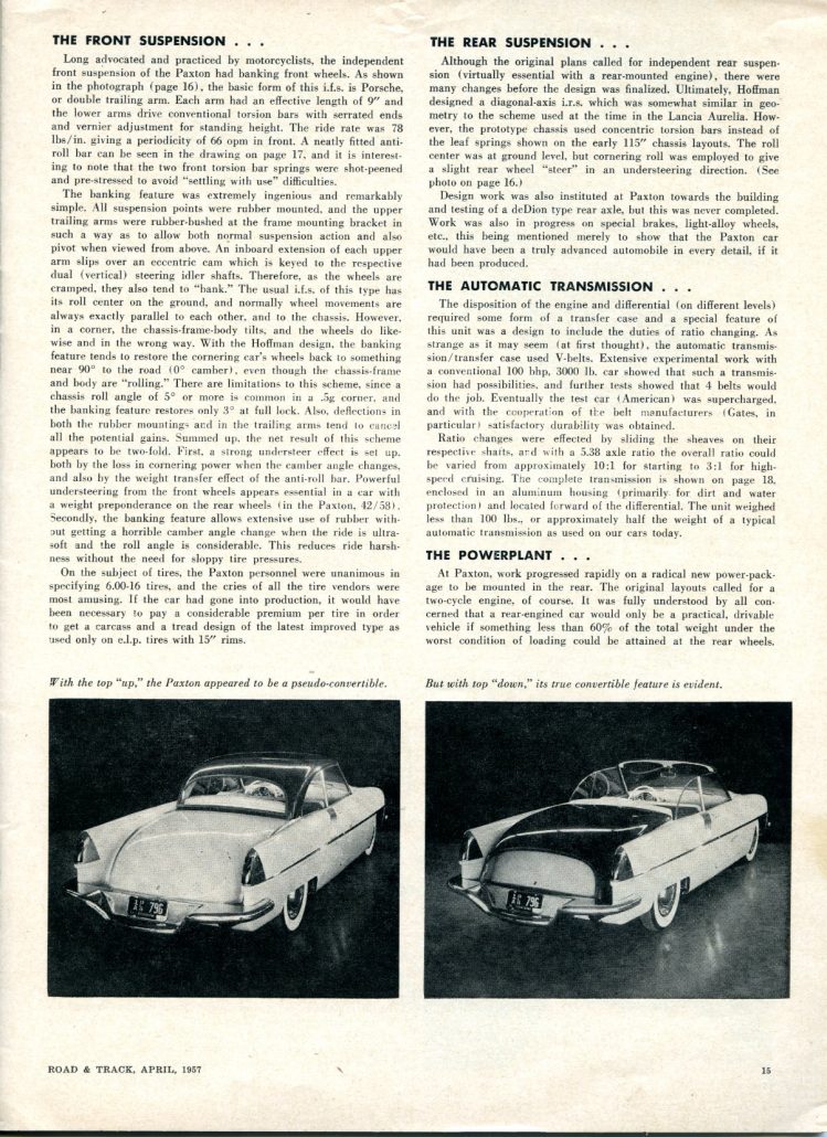
The true convertible hard-top feature was certainly logical and long overdue–again, six years ahead of its time. Its operating principle was based on a pair of small steel cables which are concealed in narrow T-slots running along each side of the trunk lid opening. When conventional windshield toggles are released an electric-powered winch pulls the top back and over the rear deck panel. The top, of course, fits very closely to the deck when “folded” and is scarcely noticed when painted the same color as the body and deck panels.
Because of this feature some compromises in top and deck contours are mandatory, and the overall design problem from the stylist’s viewpoint is not as simple as it may seem. Particularly where, as in this example, the rear passengers must have adequate headroom and a rear-mounted engine must be able to fit under the rear deck.

The Frame:
Back in Detroit, Roscoe Hoffman and his crew of designers had the difficult task of creating a frame and suspension system for a body not yet finalized, for an engine not yet running. Although this forced them to make many changes, a completed prototype chassis was built and shipped to California before a powerplant or a body were completed.
The frame for the Paxton was of a unique type, described by aircraft designers as a “torque-box.” In essence, a cross section through the floor looks much like an airplane wing with a central tunnel or duct analogous to the wing spar. Stressed skin of light gauge, rust-resistant steel forms both the floor and the underpan with gentle slopes as the floor/frame tapers from 4.5″ deep at the center to 2.5″ deep at the side rails under the doors.
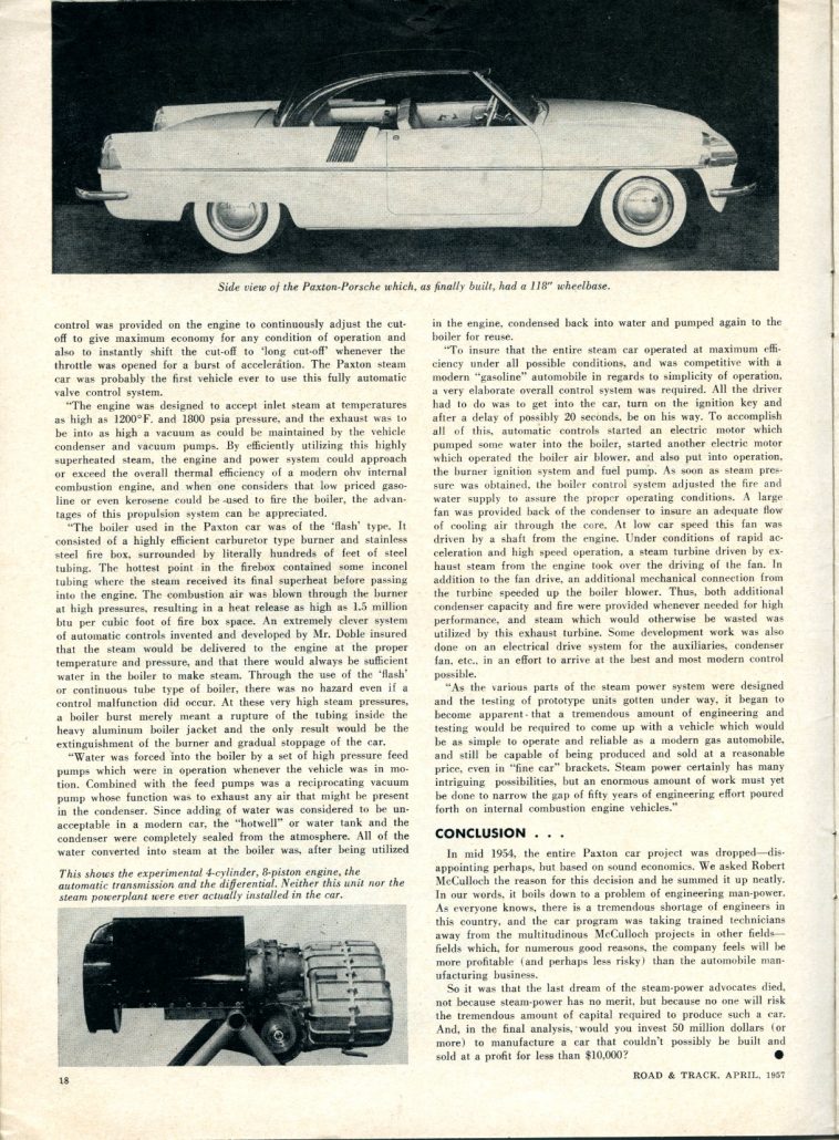
The result was a very satisfactory frame, relatively light (about 160 lbs.) and adequately rigid for use with an open-roof body which could contribute little or nothing towards resisting torsional loadings. The central duct served to supply air to the rear-mounted engine, but additional cooling air was also supplied by the stylist via an opening on each side of the body. Tests, both on a rig and on the road, showed the frame to be adequate–its torsional rigidity factor was slightly better than 3000 ft-lbs/degree, measured over the length of wheelbase (118″).
The Front Suspension
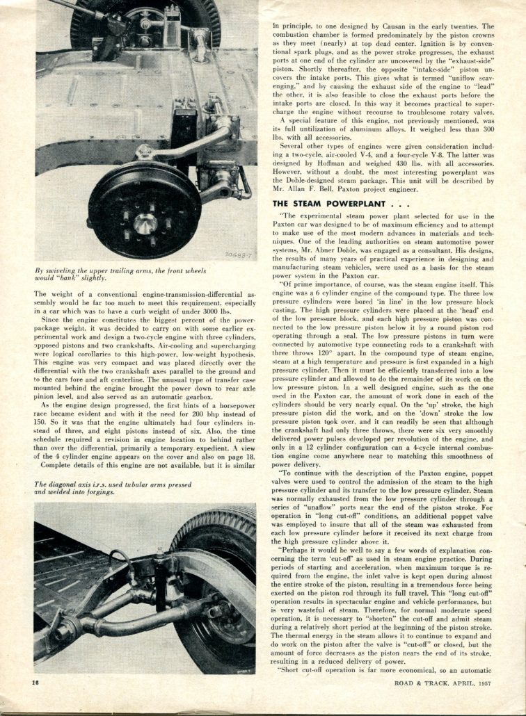
Long advocated and practiced by motorcyclists, the independent front suspension of the Paxton had banking front wheels. As shown in the photograph (page 16), the basic form of this i.f.s. is Porsche, or double trailing arm.
Each arm had an effective length of 9″ and the lower arms drive conventional torsion bars with serrated ends and vernier adjustment for standing height. The ride rate was 78 lbs/in. giving a periodicity of 66 opm in front.
A neatly fitted antiroll bar can be seen in the drawing on page 17, and it is interesting to note that the two front torsion bar springs were shot-peened and pre-stressed to avoid “settling with use” difficulties.
The banking feature was extremely ingenious and remarkably simple. All suspension points were rubber mounted, and the upper trailing arms were rubber-bushed at the frame mounting bracket in such a way as to allow both normal suspension action and also pivot when viewed from above.
An inboard extension of each upper arm slips over an eccentric cam which is keyed to the respective dual (vertical) steering idler shafts. Therefore, as the wheels are cramped, they also tend to “bank.” The usual i.f.s. of this type has its roll center on the ground, and normally wheel movements are always exactly parallel to each other, and to the chassis.
However, in a corner, the cassis-frame-body tilts, and the wheels do likewise and in the wrong way. With the Hoffman design, the banking feature tends to restore the cornering car’s wheels back to something near 90 degrees to the road (0 degrees camber), even though the classis-frame and body are “rolling.” There are limitations to this scheme, since a chassis roll angle of 5 degrees or more is common in a .5g corner, and the banking feature restores only 3 degrees at full lock. Also, deflections in both the rubber mountings and in the trailing arms tend to cancel all the potential gains.
 Summed up, the net result of this scheme appears to be two-fold. First, a strong understeer effect is set up, both by the loss in cornering power when the camber angle changes, and also by the weight transfer effect of the anti-roll bar.
Powerful understeering from the front wheels appears essential in a car with a weight preponderance on the rear wheels (in the Paxton, 42/58). Secondly, the banking feature allows extensive use of rubber without getting a horrible camber angle change when the ride is ultrasoft and the roll angle is considerable.
This reduces ride harshness without the need for sloppy tire pressures. On the subject of tires, the Paxton personnel were unanimous in specifying 6.00-16 tires, and the cries of all the tire vendors were most amusing.
If the car had gone into production, it would have been necessary to pay a considerable premium per tire in order to get a carcass and a tread design of the latest improved type as used only on e.l.p. tires with 15″ rims.
The Rear Suspension:
Although the original plans called for independent rear suspension (virtually essential with a rear-mounted engine), there were many changes before the design was finalized.
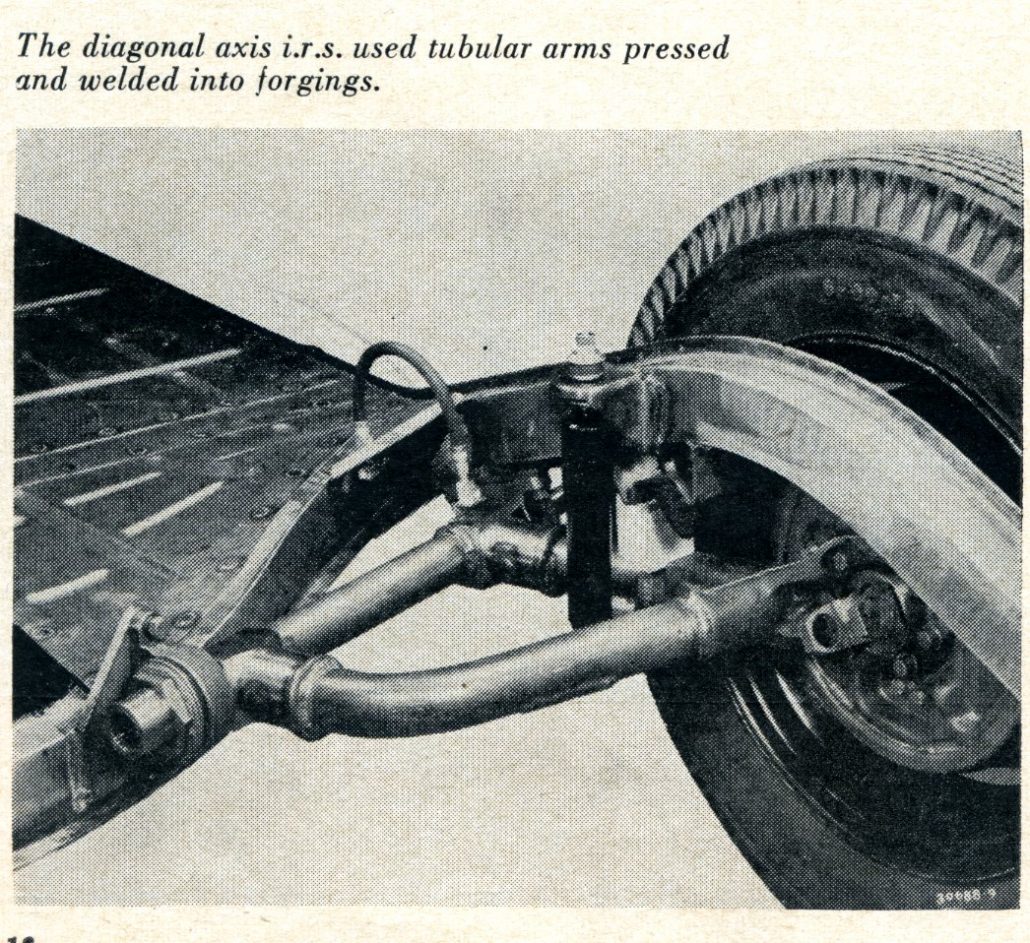
Ultimately, Hoffman designed a diagonal-axis i.r.s. which as somewhat similar in geometry to the scheme used at the time in the Lancia Aurelia. However, the prototype chassis used concentric torsion bars instead of the leaf springs shown on the early 115″ chassis layouts. The roll center was at ground level, but cornering roll was employed to give a slight rear wheel “steer” in an understeering direction. (see photo on page 16).
Design work was also instituted at Paxton towards the building and testing of a deDion type rear axle, but this was never completed. Work was also in progress on special brakes, light-alloy wheels, etc., this being mentioned merely to show that the Paxton car would have been a truly advanced automobile in every detail, if it had been produced.
The Automatic Transmission:
The disposition of the engine and differential (on different levels) required some form of a transfer case and a special feature of the unit was a design to include the duties of ratio changing. As strange as it may seem (at first thought), the automatic transmission/transfer case used V-belts.
Extensive experimental work with a conventional 100 bhp, 3000 lb. car showed that such a transmission had possibilities, and further tests showed that 4 belts would do the job. Eventually the test car (American) was supercharged, and with the cooperation of the belt manufacturers (Gates, in particular) satisfactory durability was obtained.
Ratio changes were effected by sliding the sheaves on their respective shafts, and with a 5.38 axle ratio the overall ratio could be varied from approximately 10:1 for starting to 3:1 for high-speed cruising. The complete transmission is shown on page 18, enclosed in an aluminum housing (primarily for dirt and water protection) and located forward of the differential. The unit weighed less than 100 lbs. or approximately half the weight of a typical automatic transmission as used on our cars today.
The Powerplant:
At Paxton, work progressed rapidly on a radical new power-package to be mounted in the rear. The original layouts called for a two-cycle engine, of course.
It was fully understood by all concerned that a rear-engined car would only be a practical, drivable vehicle if something less than 60% of the total weight under the worst condition of loading could be attained at the rear wheels.
The weight of a conventional engine-transmission-differential assembly would be far too much to meet this requirement, especially in a car which was to have a curb weight of under 3000 lbs. Since the engine constitutes the biggest percent of the power-package weight, it was decided to carry on with some earlier experimental work and design a two-cycle engine with three cylinders, opposed pistons and two crankshafts.
Air-cooling and supercharging were logical corollaries to this high-power, low-weight hypothesis. This engine was very compact and was placed directly over the differential with the two crankshaft axes parallel to the ground and to the cars fore and aft centerline. The usual type of transfer case mounted behind the engine brought the power down to rear axle pinion level, and also served as an automatic gearbox.
As the engine design progressed, the first hints of a horsepower race became evident and with it the need for 200 bhp instead of 150. So it was that the engine ultimately had four cylinders instead of three, and eight pistons instead of six. Also, the time schedule required a revision in engine location to behind rather than over the differential, primarily a temporary expedient. A view of the 4 cylinder engine appears on the cover and also on page 18.
Complete details of this engine are not available, but it is similar in principle, to one designed by Causan in the early twenties. The combustion chamber is formed predominately by the piston crowns as they meet (nearly) at the top dead center. Ignition is by conventional spark plugs, and as the power stroke progresses, the exhaust ports at one end of the cylinder are uncovered by the “exhaust-side” piston. Shortly thereafter, the opposite “intake-side” piston uncovers the intake ports.
 This gives what is termed “uniflow scavenging”, and by causing the exhaust side of the engine to “lead” intake ports are closed. In this way it becomes practical to supercharge the engine without recourse to troublesome rotary valves. A special feature of this engine, not previously mentioned, was its full utilization of aluminum alloys.
It weighed less than 300 lbs. with all accessories. Several other types of engines were given consideration including a two-cycle, air-cooled V-4, and a four-cycle V-8.
The latter was designed by Hoffman and weighed 430 lbs. with all accessories. However, without a doubt, the most interesting powerplant was the Doble-designed steam package. This unit will be described by Mr. Allan F. Bell, Paxton project engineer.
The Steam Powerplant:
“The experimental steam power plant selected for use in the Paxton car was designed to be of maximum efficiency and to attempt to make use of the most modern advances in materials and techniques. One of the leading authorities on steam automotive power systems, Mr. Abner Doble, was engaged as a consultant. His designs, the results of many years of practical experience in designing and manufacturing steam vehicles, were used as a basis for the steam power system in the Paxton car.
“Of prime importance, of course, was the steam engine itself. This engine was a 6 cylinder engine of the compound type. The three low pressure cylinders were bored “in line” in the low pressure block casting. The high pressure cylinders were placed at the “head” end of the low pressure block, and each high pressure piston was connected to the low pressure piston below it by a round piston rod operating through a seal.
The low pressure pistons in turn were connected by automotive type connecting rods to a crankshaft with three throws 120 degrees apart. In the compound type of steam engine, steam at a high temperature and pressure is first expanded in a high pressure cylinder. Then it must be efficiently transferred into a low pressure cylinder and allowed to do the remainder of its work on the low pressure piston. In a well designed engine, such as the one used in the Paxton car, the amount of work done in each of the cylinders should be very nearly equal.
On the ‘up’ stroke, the high pressure piston did the work, and on the ‘down’ stroke the low pressure piston took over, and it can readily be seen that although the crankshaft had only three throws, there were six very smoothly delivered power pulses developed per revolution of the engine, and only in a 12 cylinder configuration can a 4-cycle internal combustion engine come anywhere near to matching this smoothness of power delivery. 
“To continue with the description of the Paxton engine, poppet valves were used to control the admission of the steam to the high pressure cylinder and its transfer to the low pressure cylinder. Steam was normally exhausted from the low pressure cylinder through a series of “unaflow” ports near the end of the piston stroke.
For operation in “long cut-off” conditions, an additional poppet valve was employed to insure that all of the steam was exhausted from each low pressure cylinder before it received its next charge from the high pressure cylinder above it.
“Perhaps it would be well to say a few words of explanation concerning the term ‘cut-off’ as used in steam engine practice. During periods of starting and acceleration, when maximum torque is required from the engine, the inlet valve is kept open during almost the entire stoke of the piston, resulting in a tremendous force being exerted on the piston rod through its full travel.
This “long cut-off” operation results in spectacular engine and vehicle performance, but is very wasteful of steam. Therefore, for normal moderate speed operation, it is necessary to “shorten” the cut-off and admit steam during a relativesly short period at the beginning of the piston stroke. The thermal energy in the steam allows it to continue to expand and do work on the piston after the valve is “cut-off” or closed, but the amount of force decreases as the piston nears the end of its stroke, resulting in a reduced delivery of power.
“Short cut-off operation is far more economical, so an automatic control was provided on the engine to continuously adjust the cut-off to give maximum economy for any condition of operation and also to instantly shift the cut-off to ‘long cut-off’ whenever the throttle was opened for a burst of acceleration. The Paxton steam car was probably the first vehicle ever to use this fully automatic valve control system.
“The engine was designed to accept inlet steam at temperatures as high as 1200 degrees F. and 1800 psia pressure, and the exhaust was to be into as high a vacuum as could be maintained by the vehicle condenser and vacuum pumps.

By efficiently utilizing this highly superheated steam, the engine and power system could approach or exceed the overall thermal efficiency of a modern ohv internal combustion engine, and when one considers that low priced gasoline or even kerosene could be used to fire the boiler, the advantages of this propulsion system can be appreciated.
“The boiler used in the Paxton car was of the ‘flash’ type. It consisted of a highly efficient carburetor type burner and stainless steel fire box, surrounded by literally hundreds of feet of steel tubing. The hottest point in the firebox contained some inconel tubing where the steam received its final superheat before passing into the engine. The combustion air was blown through the burner at high pressures, resulting in a heat release as high as 1.5 million btu per cubic foot of fire box space.
An extremely clever system of automatic controls invented and developed by Mr. Doble insured that the steam would be delivered to the engine at the proper temperature and pressure, and that there would always be sufficient water in the boiler to make steam. Through the use of the ‘flash’ or continuous tube type of boiler, there was no hazard even if a control malfunction did occur. At these very high steam pressures, a boiler burst merely meant a rupture of the tubing inside the heavy aluminum boiler jacket and the only result would be the extinguishment of the burner and gradual stoppage of the car.
“Water was forced into the boiler by a set of high pressure feed pumps which were in operation whenever the vehicle was in motion. Combined with the feed pumps was a reciprocating vacuum pump whose function was to exhaust any air that might be present in the condenser.
Since adding of water was considered to be unacceptable in a modern car, the “hotwell” or water tank and the condenser were completely sealed from the atmosphere. All of the water converted into steam at the boiler was, after being utilized in the engine, condensed back into water and pumped again to the boiler for reuse.
“To insure that the entire steam car operated at maximum efficiency under all possible conditions, and was competitive with a modern “gasoline” automobile in regards to simplicity of operation, a very elaborate overall control system was required. All the driver had to do was to get into the car, turn on the ignition key and after a delay of possibly 20 seconds, be on his way.
To accomplish all of this, automatic controls started an electric motor which pumped some water into the boiler, started another electric motor which operated the boiler air blower, and also put into operation, the burner ignition system and fuel pump.
 As soon as steam pressure was obtained, the boiler control system adjusted the fire and water supply to assure the proper operation conditions. A large fan was provided back of the condenser to insure an adequate flow of cooling air through the core. At low car speed this fan was driven by a shaft from the engine.
Under the conditions of rapid acceleration and high speed operation, a steam turbine driven by exhaust steam from the engine took over the driving of the fan. In addition to the fan drive, an additional mechanical connection from the turbine speeded up the boiler blower.
Thus, both additional condenser capacity and fire were provided whenever needed for high performance, and steam which would otherwise be wasted was utilized by this exhaust turbine. Some development work was also done on an electrical drive system for the auxiliaries, condenser fan, etc. in an effort to arrive at the best and most modern control possible.
“As the various parts of the steam power system were designed and the testing of prototype units gotten under way, it began to become apparent that a tremendous amount of engineering and testing would be required to come up with a vehicle which would be as simple to operate and reliable as a modern gas automobile, and still be capable of being produced and sold at a reasonable price, even in “fine car” brackets.
Steam power certainly has many intriguing possibilities, but an enormous amount of work must yet be done to narrow the gap of fifty years of engineering effort poured forth on internal combustion engine vehicles.”
Conclusion:
In mid 1954, the entire Paxton car project was dropped–disappointing perhaps, but based on sound economics. We asked Robert McCulloch the reason for this decision and he summed it up neatly. In our words, it boils down to a problem of engineering man-power.
As everyone knows, there is a tremendous shortage of engineers in this country, and the car program was taking trained technicians away from the multitudinous McCulloch projects in other fields–fields which, for numerous good reasons, the company feels will be more profitable (and perhaps less risky) than the automobile manufacturing business.
So it was that the last dream of the steam-power advocates died, not because steam-power has no merit, but because no one will risk the tremendous amount of capital required to produce such a car.
And, in the final analysis, would you invest 50 million dollars (or more) to manufacture a car that couldn’t possibly be built and sold at a profit for less than $10,000?
Summary:
Steam power never became a reality for the Paxton. Instead, the Paxton Phoenix kept the original Porsche powerplant that had been installed for testing purposes. Recently, this very special car was shown at the 2011 Milwaukee Masterpiece Concours d’ Elegance. We’ll feature photos of the Paxton at the Milwaukee Masterpiece Concours d’ Elegance in a future story here at Forgotten Fiberglass.
Hope you enjoyed the story, and until next time…
Glass on gang…
Geoff
——————————————————————-
Click on the Images Below to View Larger Pictures
——————————————————————-

Thanks for putting this up; for sometime I’ve wondered about the proposed 2-stroke engine, having seen a brief mention of it in publications. John Bond’s description is helpful, especially his comment that it is like N. Causan’s, which, as I recall, was reported to produce 136 hp from a 1.5-litre four-cylinder engine, thus making the Paxton figure of 200 hp look feasible given improvements in materials, supercharging and fuels, etc..
Thank you for posting this information. The Virtual Steam Car Museum had a few bits of Paxton material, but not much. I cited your page and linked it from the VSCM Paxton page, which should be up in a few h ours.
Very best wishes!
Don Hoke
The Virtual Steam Car Museum, Inc.
It is likely that today a steam engine for range extending could be used in a series hybrid. Since the fuel being burned is operating at close to atmospheric pressure the NOx production should be considerably lower than in an internal combustion engine.
Very remarkable car and engineering studies. It is trully a shame that a car with this much forward design and technology was not brought to a finish and produced even on a limited scale.
The series of Pelland steamers by Peter Pellandine, fiberglass guru of Lotus in the early days, are well worth opening a thread of their own. Peter is still alive and many articles on his cars are on the steamautomobile.com website.
Brooks Stevens was probably the ultimate industrial designer whose many products we have had the opportunity to see. He designed many things other than automobiles, one of which was a French train. He told me that the main requirement was to be able to stand in the club car with a drink in your hand at 120 MPH and not spill it. One great man that we lost way too early. A real gentleman!
Absolutely one of the best early designs, the front suspension reminds me of aston martins db4 trailing link setup.the rear early panhard ,to bad they did not develop a gas engine for this car mike
I remember the Gvang steam car, but I don’t think it was from Great Britain – I believe it was from Australia – it was first shown there in 1973.
The Paxton was not only interesting but incredibly innovative as well. Very easy on the eyes, and it would be interesting to see a modern take on a steam vehicle… any one remember the Gvang from Great Britain in the 70’s