


Hi Gang…
This article was a very important article for John Bond – new owner of Road and Track Magazine as of November 1952 – just three months prior to this article’s publication. How could I know this article was incredibly important to Bond?
Last year I had the chance to travel to Kettering University in Flint Michigan and spent several days going thru John Bond’s archive. And there, nearly 60 years after the article had been published, were all the notes, pictures, and iterations of the article – confirming the detail that he wanted to share in making the information about “building a fiberglass body” as accurate as he could for the American public.
John Bond was a “man with a ‘fiberglass’ plan.”
But reading the article reveals more information. Both Chuck Manning and Richard Voss contributed to this article and at least one picture of Chuck Manning and Rod Schapel appear showing the precision required to produce fiberglass parts correctly when creating a body to be used on a sports car (see below).

Keep in mind this was article was published just 14 months after fiberglass bodies debuted at the November ’51 Petersen Motorama in Los Angeles, California. This is a very early article from one of the leading automotive magazines and publishers, and gives us a window into the thinking and strategy of fiberglass and building your own custom body from “back in the day.”
John Bond also covered 6 places where you could buy bodies and simplify building your own sports cars. These companies included:
- Glasspar
- Plastic Age Company (more about this organization at the end of this story)
- Viking-Craft Company
- Vale Wright
- Atlas
- Lancer

Interesting, he did not mention other companies which were established or “fledgling” which included:
- American Enterprises
- Frazen
- LaSaetta
- Maverick
- Sportstar
- Woodill Wildfire
- Victress
- BMC Singer
- Vaughan Singer
Most of these companies were just getting started and would blossom in ’53, but I thought it would be interesting to see what “wasn’t” mentioned, and where research has shown that the companies in the above list were in production in ’52.

Pictures Shown in Article:
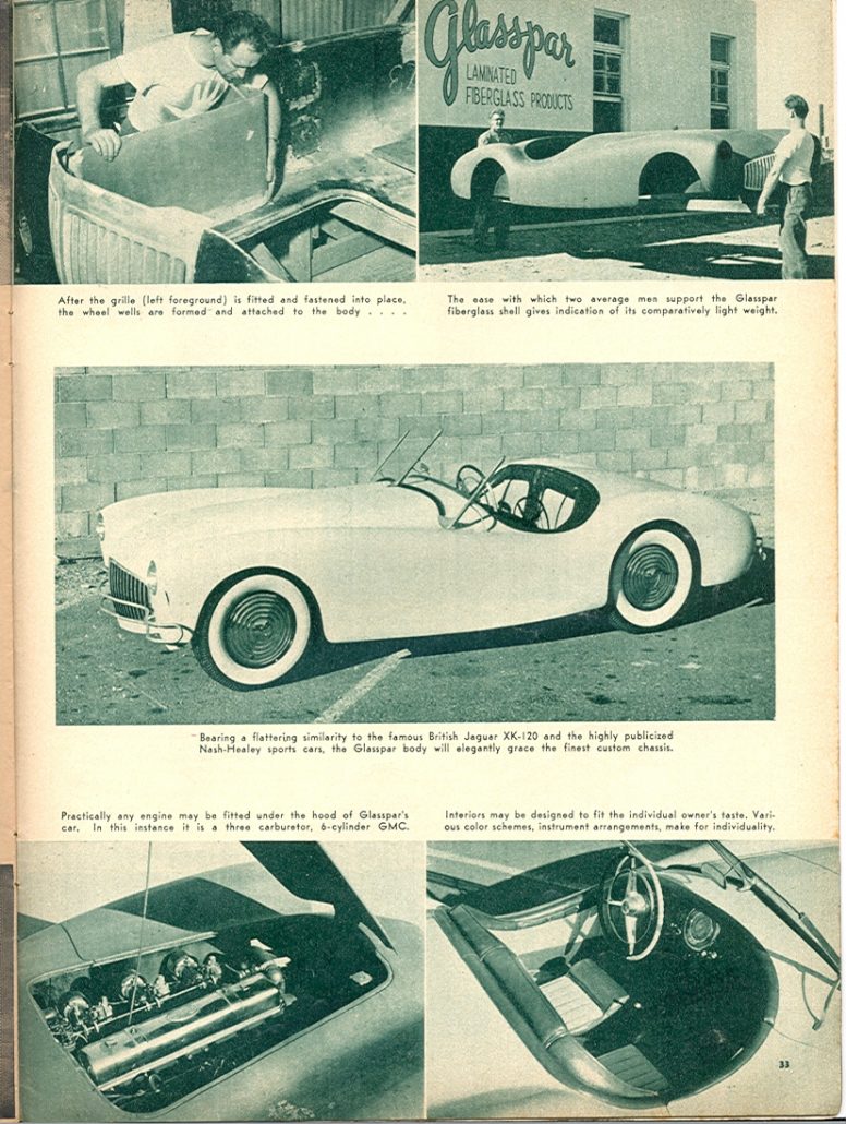
Be sure to closely review the photos that are shown in the article. These are wonderful in what they show and the details shared in their captions. Great photos exist of the new Atlas bodies – and a nearly finished coupe which may have been the car that is shown in one of Allied’s brochures (look how far back the steering wheel is in the photo!). Click here to test your skill and match the car.
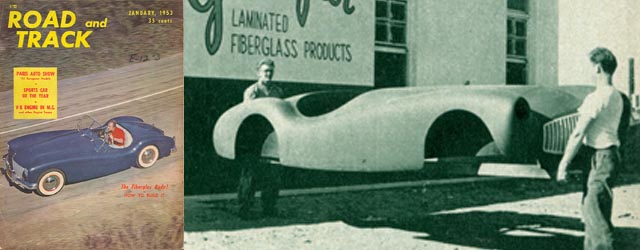
Also shown is a photo of the Chuck Manning Special being built. And…photos of a Glasspar G2 being layed up, another one being cured, and one being carried just outside the Glasspar factory. I wonder which Glasspar G2 is shown with the GMC 6 cylinder engine? I think it’s the Don Cook G2? Click here and let me know what you think.
I can confirm that the interior of the Glasspar G2 shown is NOT the Don Cook G2. Any ideas on which interior car belongs to gang?
So…have at it… read and enjoy the article below in magnificent detail. And remember… as with every image here at Forgotten Fiberglass, you can click directly on the photo and make it appear larger on your screen.
Off you go gang!

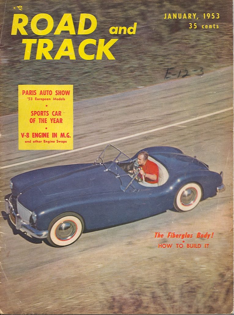
How To Build a Fiberglass Body
Road and Track: January 1953
By John Bond, Technical Editor; Road and Track Magazine
Editor’s note: The technique and usage of this relatively new material is still in a state of flux, and new developments occur almost daily. We are indebted to Richard H. Voss and Charles G. Manning, both of whom submitted articles on the subject. Some of their material is incorporated in this article.
A great deal has been written on the subject of plastic and fiberglass bodies, and much of the information given, although written only recently, is already obsolete. This situation is brought about by prodigious research being carried on by many large industrial organizations, particularly the suppliers of raw materials.
This article will be restricted to a discussion of reinforced plastics as applied to custom and very limited production automobile bodies. Furthermore, the reinforcing material under discussion will be glass cloth. Many other reinforcing materials, such as paper, fabrics, and rope fibers, can and have been used for various applications, but for our purpose glass cloth is the best material so far developed.

The resins which are used to impregnate the cloth will, in this article, be confined to those in the polyester group, capable of curing at normal room temperature without pressure.
As with the choice of basic materials, there are many possible methods of constructing a reinforced plastic body. The simplest method is to apply glass cloth and resin directly over a form. The results from this method have not been too successful, and the amount of disc sanding and hand finishing required is tremendous. The best and only recommended method involves these six basic steps (see figures 1 thru 6):
- Make the body loft
- Construct the wood buck
- Construct the male form
- Construct the female mold
- Lay-up the body panels
- Assemble the body

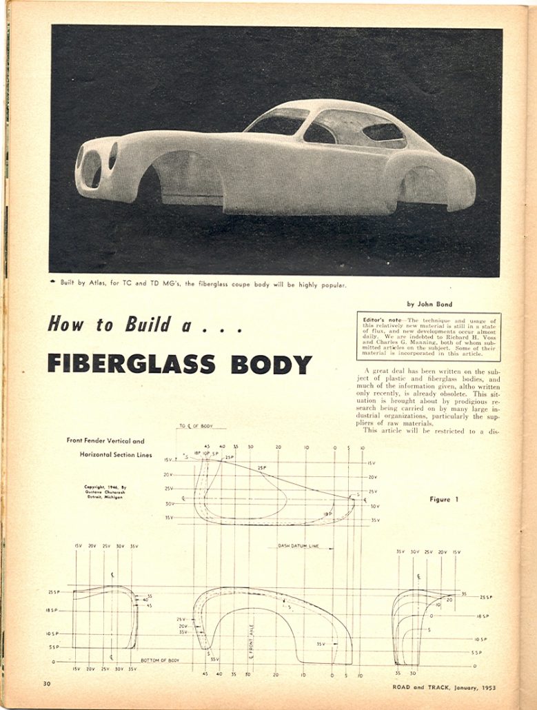
Step 1: Making The Body Loft
Most articles on fiberglass bodies seem to omit any reference to this most important step in body construction. How can anyone carry out steps 2 and 3 unless he knows to what shape and dimensions the templates must be cut? (See Fig. 1) Even the amateur boat builder must use a good set of plans and a table of offsets if he is to achieve any measure of success.
The loft is a 3-view drawing showing the body contours. Figure 1 shows a typical loft of a front fender. The reference department of most public libraries contain books on boat building which outline the rudiments of lofting. Books on aircraft lofting procedures are also helpful. If you are lucky you may even find “Automobile Body Engineering and Surface Development” by Gustave Chutorash (no longer in print).
Because making a loft is a highly specialized skill, another alternative must often be used. This involves the construction of a scale model to at least 1/10 actual size, and preferably to 1/4 actual size. The scale model can be made of clay, wood, or plaster. Taking off templates requires accurate work because errors are multiplied by the scale.
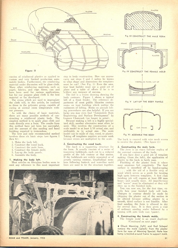
Step 2: Constructing The Wood Buck
The buck is a supporting structure for the form. It usually consists of a series of transverse bulkheads, each cut to a reduced profile of the loft contour at that station. If the bulkheads are widely separated or of greatly varying contour, longitudinal members following buttock and waterline mold lines are used to tie the structure together. The buck is covered with wire mesh screen to receive the plaster. (See figure 2.)

Step 3: Constructing The Male Form
The form is an exact full-size replica of the external contours of the body. If you have done a good job of template making (from the loft), the application of plaster to the buck is fairly easy.
Finishing of the plaster form is where most amateurs fail completely. The final surface is smoothed off by hand-scraping….with the aid of a flexible strip of wood which serves as a guide for locating high spots between templates. A first class finishing job will require at least 200 man hours–and usually more. All imperfections and “waves” must be eliminated or they will show up in the finished body.
You can now see, for the first time, exactly how your finished body will look. Changes in contour should be made by chipping the plaster out of the section to be altered because adding plaster to a smooth, dried surface is not feasible. After final sanding, the form is allowed to dry for several days. It is then given a coat of ordinary sanding sealer followed by a waxing with auto body wax (paste).
Step 4: Constructing The Female Molds
The female mold is an exact duplicate of the completed male form in reverse. It is made by using the male form as the pattern. If the female mold is made of plaster, it is often called a “splash,” particularly if the body is divided into smaller sections. Separate sections eliminate the need for a 5-ton derrick to hoist a one piece mold from the form.
The mold can also be made of fiberglass, which is more costly, but has the advantage of less weight to handle and no danger of breakage. If more than one identical body is to be made, a fiberglass mold is almost mandatory because plaster gives trouble with sticking and occasionally must be broken up to get the body part out.
Another advantage of fiberglass for the mold has to do with the matter of draft. (The open “top” of the mold must be larger than the closed “bottom”–like mom’s jelly mold.) If the mold is one piece, and in plaster, it must have draft angles which imposes definite limitations on body contours.
With fiberglass molds it is possible to “spring” the material enough to give some latitude in this direction. For example: the Glasspar body is made in one piece, from a one-piece mold…yet it has a “rolled under” lower edge.
Regardless of whether plaster or fiberglass is used for the mold, wood or metal frames are necessary for strength and rigidity. For plaster, loose hemp is added to the mix after the facing cost is applied. This both strengthens and lightens the mold. Hemp dipped in plaster is twisted into rope and worked around the supporting frame to tie the two together. This is illustrated in the photograph on page 31.

If fiberglass is to be used for making the mold or molds, follow the instructions given under Step 5, but use twice as many layers of cloth, mat, and resin to insure rigidity. The “carrying frame” can be made up later if desired, and attached to the mold with narrow strips of cloth and more resin. The frame should be added before the mold is pulled from the form as it will prove quite useful if there is any tendency towards sticking.
The interior surfaces of the mold or splash sections must be repaired where necessary and sealed if they are of plaster. Remember that the perfection of these surfaces determines the quality of the finish on the final body.
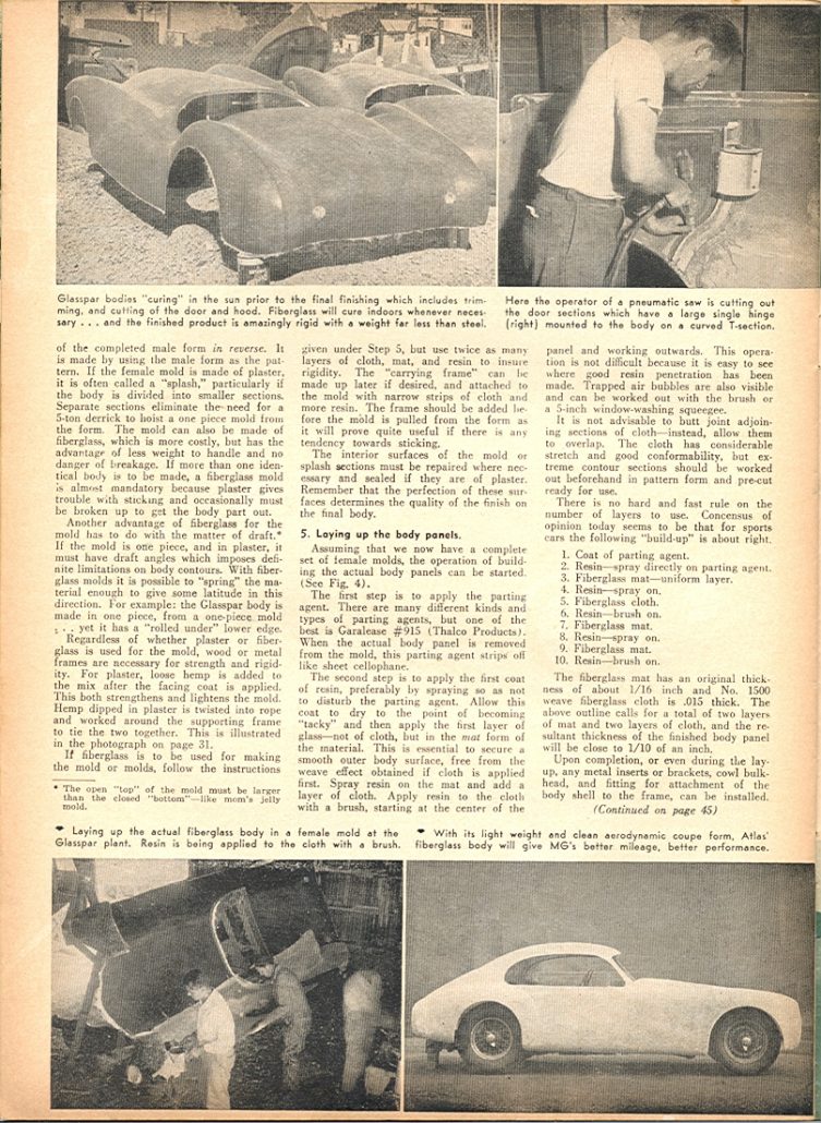
Step 5: Laying Up The Body Panels
Assuming that we now have a complete set of female molds, the operation of building the actual body panels can be started. (See Fig. 4).
The first step is to apply the parting agent. There are many different kinds and types of parting agents, but one of the best is Garalease #915 (Thalco Products). When the actual body panel is removed from the mold, this parting agent strips off like sheet cellophane.
The second step is to apply the first coat of resin, preferably by spraying so as not to disturb the parting agent. Allow this coat to dry to the point of becoming “tacky” and then apply the first layer of glass–not of cloth, but in the mat form of the material.
This is essential to secure a smooth outer body surface, free from the weave effect obtained if cloth is applied first. Spray resin on the mat and add a layer of cloth. Apply resin to the cloth with a brush starting at the center of the panel and working outwards.

This operation is not difficult because it is easy to see where good resin penetration has been made. Trapped air bubbles are also visible and can be worked out with the brush or a 5-inch window-washing squeegee.
It is not advisable to butt joint adjoining sections of cloth–instead, allow them to overlap. The cloth has considerable stretch and good conformability, but extreme contour sections should be worked out beforehand in pattern form and pre-cut ready for use.
There is no hard and fast rule on the number of layers to use. Consensus of opinion today seems to be that for sports cars the following “build-up” is about right.
- Coat of parting agent
- Resin–spray directly on parting agent
- Fiberglass mat–uniform layer
- Resin–Spray on
- Fiberglass cloth
- Resin–brush on
- Fiberglass mat
- Resin–spray on
- Fiberglass mat
- Resin–brush on

The fiberglass mat has an original thickness of about 1/16 inch and No. 1500 weave fiberglass cloth is .015 thick. The above outline calls for a total of two layers of mat and two layers of cloth, and the resultant thickness of the finished body panel will be close to 1/10 of an inch.
Upon completion, or even during the lay-up, any metal inserts, or brackets, cowl bulkhead, and fitting for attachment of the body shell to the frame can be installed. These should be drilled and tapped before use, if possible.
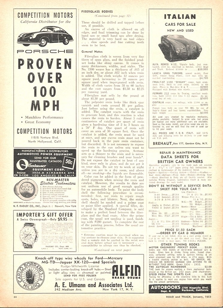
An excess of cloth is allowed on all edges, and final trimming can be done by band saw or small hand saw after drying. The material is very hard on tool edges…slow speeds and fine cutting teeth seem to be best.
General Notes:
Fiberglass cloth is woven from very fine fibers of spun glass, and the finished product looks like shiny canvas. It comes in many thicknesses, widths, and styles. The No. 1500 weave has a thickness of .015 of an inch dry, or about .022 inch when resin is added.
The cloth weighs 12 ounces per square yard, increasing to 28 ounces per square yard when impregnated with resin. Width of cloth varies from 38 to 60 inches and the cost ranges from $1.50 to $2.25 per running yard. Fiberglass mat sells by the pound at about $1.30 per pound.
The polyester resin looks like thick spar varnish and costs around $1 per gallon. Just before using the resin, a catalyst is added. The catalyst reacts with the resin to generate heat, and this action is what causes the resin to harden. About 5 cubic centimeters of catalyst per quart of resin gives a hardening time of 2 to 3 hours on a 70 degree F day.
One quart of resin will cover an area of 30 square feet. Once the catalyst is added, the resin must be used at once, and any excess resin must not be poured back in the pure resin container, but discarded. It is not necessary to expose the resin to the sun unless you want to speed up the hardening process. Acetone acts as a thinner to the resin and is necessary for cleaning brushes and your hands.
Do not expose the catalyst to heat of any kind, store only in glass, and do not get it on your skin. Do not try to work at night unless you are in a dry room, and above all–no smoking–the liquids are flammable.
Color can be added in the form of powdered pigments when mixing the resin and catalyst. However, the results to date are not uniform nor of good enough quality for an automobile body. To paint the body shell the following procedure is recommended: first, use resin to repair rough spots, holes, and blisters.
Next, the entire shell should be sanded and a prime coat or paint filler applied. A special filler, developed by the Stanford Company, is said to make a perfect bond between the fiberglass and the final coats. After the prime coat, the usual wet sanding is used, finishing with #280 garnet. To complete the rest of the painting process, follow the usual automotive practice.
In conclusion, it should be obvious that there is a great deal more to building a fiberglass body than can be covered in this article. The final result is dependent upon your experience, skill, and patience. Manufacturers of fiberglass aircraft components who now have several years of experience admit that they still face problems and that uniform results are often unaccountably impossible to achieve.
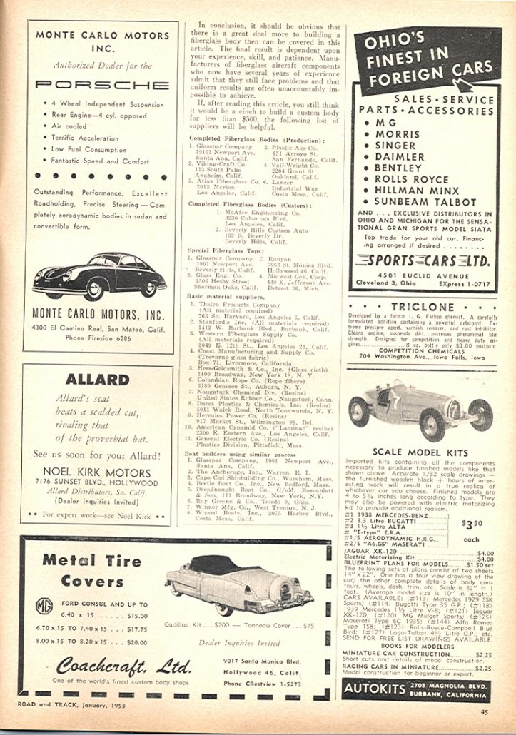
If, after reading this article, you still think it would be a cinch to build a custom body for less than $500, the following list of suppliers will be helpful.

Completed Fiberglass Bodies (Production):
- Glasspar Company, 19101 Newport Avenue, Santa Ana, California
- Plastic Age Company, 651 Arroyo Street, San Fernando, California
- Viking-Craft Company, 113 South Palm, Anaheim, California
- Vale-Wright Company, 2204 Grant Street, Oakland, California
- Atlas Fiberglass Company, 2015 Marion, Los Angeles, California
- Lancer, Industrial Way, Costa Mesa, California
Completed Fiberglass Bodies (Custom):
- McAfee Engineering Company, 3230 Cahuenga Blvd, Los Angeles, California
- Beverly Hills Custom Auto, 139 S. Beverly Drive, Beverly Hills, California
Special Fiberglass Tops:
- Glasspar Company, 1901 Newport Avenue, Santa Ana, California
- Runyan, 7966 St. Monica Blvd. Hollywood 46, California
- Glass Eng. Co. 1506 Hesby Street, Sherman Oaks, California
- Midwest Gen. Corporation, 440 E Jefferson Avenue, Detroit 26, Michigan
Basic Material Suppliers:
- Thalco Products Company (All material required) 766 S. Harvard, Los Angeles 5, California
- Stanford’s Inc. (All materials required) 1412 W. Burbank Blvd., Burbank, California
- Western Fiberglass Supply Company (All materials required) 3049 E 12th St., Los Angeles, California
- Coast Manufacturing and Supply Company (Trevarno glass fabric) Box 71, Livermore, California
- Hess-Goldsmith & Co., Inc. (Glass cloth) 1400 Broadway, New York 18, New York
- Columbian Rope Co. (Rope Fibers) 3180 Genesee St., Auburn, New York
- Naugatuck Chemical Div. (Resins) U.S. Rubber Co. Naugatuck, Connecticut
- Durez Plastics & Chemicals Inc. (Resins) 5011 Walck Road, N. Tonawanda, New York
- Hercules Power Co. (Resins) 917 Market St., Wilmington 99, Delaware
- American Cynamid Co. (Laminac resins) 2300 E Eastern Ave., Los Angeles, California
- General Electric Co. (Resins) Plastics Division, Pittsfield, Massachusetts

Boat Builders Using Similar Process:
- Glasspar Company, 1901 Newport Ave., Santa Ana, California
- The Anchorage, Inc., Warren, Rhode Island
- Cape Cod Shipbuilding Co., Wareham, Massachusetts
- Beetle Boat Co., Inc., New Bedford, Massachusetts
- Dreadnaught Boat Co., C/om. Rosenblatt & Son, 111 Broadway, New York, New York
- Ray Greene & Co., Toledo 9, Ohio
- Winner Mfg. Co., West Trenton, New Jersey
- Wizard Boats, Inc., 2075 Harbor Blvd., Costa Mesa, California
Summary:
I’m honored to share such a comprehensive article and one that covers such technical ground with finesse and precision. Those who read this article back in ’53 and were interested in creating their own fiberglass body – or buying an existing one – were off and running after reading this tome.
But at least two questions remain. These focus on two companies where there remains scant information, and these are:
- Plastic Age Company: 651 Arroyo Street San Fernando, California
- Beverly Hills Custom Auto: 139 S. Beverly Drive. Beverly Hills, California
I have reason to believe that Plastic Age Company may be the producers of the mysterion that Rick D’Louhy and I call the “California Special.” I’ve seen literature from this company twice (letters) – but no photos remained with their literature – even though the letters showed “photos attached of car.” So we may find something yet 🙂
As for Beverly Hills Custom Auto, I’ve found ads for them but nothing else. Here are two ads that I’ve found showing their connection to fiberglass. Look how they offer to build bodies of fiberglass, steel, or aluminum. And… custom chassis of two different types for interested patrons. I’m sure they built some cars. Which ones did they build, gang?


It’s also interesting to note that in the section titled “Basic Material Suppliers,” Thalco is mentioned, but not Allied Products Engineering Corporation. “Allied” was the primary supplier for Victress until Ted Kelly closed his company. “Thalco” then became the primary supplier for Victress. Merrill Powell estimates this occurred in the ’54 to ’55 timeframe.
Hope you enjoyed the story, and until next time…
Glass on gang…
Geoff
——————————————————————-
Click on the Images Below to View Larger Pictures
——————————————————————-
Fiberglass has been around a lot longer that most people realize. It is interesting how long it takes certain things like industrial plastics anaheim or fiberglass to become common knowledge. I still need to get more information but it was a nice starting point. Do you know what would be the best sources to look at– to explain to my 12 year-old son?
Interesting that Bond’s article does not mentiion Victress or the Boyce-Smith Co. Doc would have already been in business, and bodies for both the Guy Mabee Special and Virgil Rice’s “Johnny Dark” car would have been produced, as well as some others. Any ideas, Geoff?
The two Atlases look different to me. The finished one has phony wheel covers while the “project” has real wire wheels.
Also note the blocks of wood supporting the body in the project photo!